Toronto, Ontario--(Newsfile Corp. - May 12, 2026) - Coyote Copper Mines Inc. (TSXV: CCMM) ("CCMM" or the "Corporation") is pleased to report the completion and preliminary interpretation of its integrated geophysical and hyperspectral program at the Copper Springs and Gibson claim packages in Arizona.
The results collectively point toward the potential presence of a large, well-developed porphyry copper system, with geophysical signatures that may exceed the scale typically observed in comparable global deposits. This work completes a major component of CCMM's 2026 exploration plan, which included drone magnetics, hyperspectral satellite imaging, CSEM, MT, 3D IP surveys, and soil geochemistry, as well as geological mapping, sampling, and relogging of historical drill core.
"A Potentially Large Porphyry System Emerging From the Data"
In CCMM'S press releases dated April 9, and April 16, 2026, CCMM outlined its exploration plans.
CCMM initiated a multi-disciplinary exploration program including:
- Hyperspectral Satellite Surveys
- Drone Magnetic Surveys
- MT and 3D IP geophysical surveys
- Relogging of historical drill core
- Soil Sampling
- Mapping, logging, and chip sampling
- Channel sampling
- Drill permits
- Drilling
The purpose of this preliminary work was to help us optimize the drill locations.
CEO Dan Weir commented: "The geophysical information has returned results better than we expected. The Drone Magnetics are showing a massive magnetic low, and the 3D MT-IP geophysics are showing a 'Donut shape' around the Magnetic low."
Weir added: "Many large mining companies look for donut-shaped geophysical anomalies. Normally the donut shapes are 2-3 km in size; we are interpreting an anomaly that is much larger."
This observation is significant. In global porphyry exploration, donut anomalies of 2-3 km are associated with major copper systems, such as those in Chile, Peru, and the southwestern United States. CCMM's anomaly appears to exceed this scale, suggesting the potential for a large mineralized footprint.
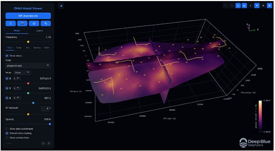
Controlled-Source Electromagnetic (CSEM) and Magnetotelluric (MT) with 3D Induced Polarization (IP) Inversion
To view an enhanced version of this graphic, please visit:
https://images.newsfilecorp.com/files/8516/296914_e1e4f1acc48e7bf5_001full.jpg
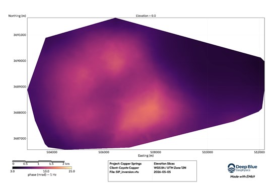
In the picture above you can see the classic Donut shaped pattern, present on CCMM's projects. The L shapes are locations of the transmitters, and the crosses were the receivers. It is the IP Inversion, depth slice being shown at 800m elevation.
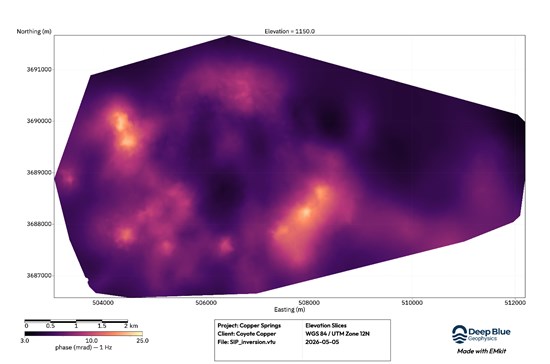
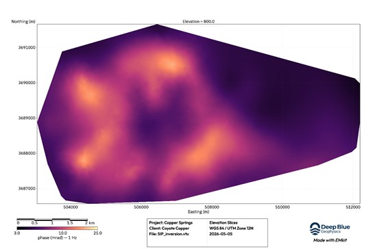
IP Inversion Results From Surface - Indication of a second Donut shape to the east
To view an enhanced version of this graphic, please visit:
https://images.newsfilecorp.com/files/8516/296914_e1e4f1acc48e7bf5_002full.jpg
300 metres deep
To view an enhanced version of this graphic, please visit:
https://images.newsfilecorp.com/files/8516/296914_e1e4f1acc48e7bf5_003full.jpg
650 metres deep
To view an enhanced version of this graphic, please visit:
https://images.newsfilecorp.com/files/8516/296914_e1e4f1acc48e7bf5_004full.jpg
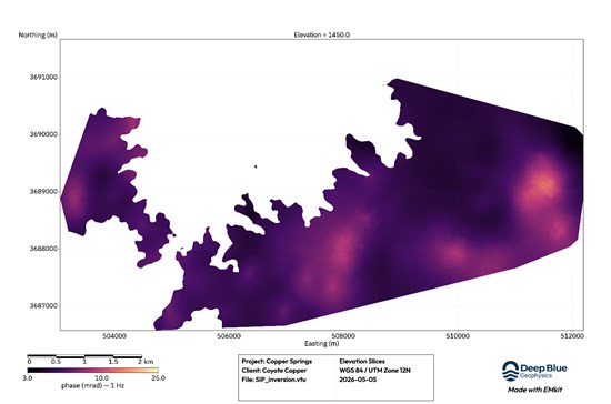
Still present at 1450 metres deep. Due to the depth we start to lose resolution
To view an enhanced version of this graphic, please visit:
https://images.newsfilecorp.com/files/8516/296914_e1e4f1acc48e7bf5_005full.jpg
What is a "Donut" Geophysical Anomaly? Also known as the "BHP Donut"
- Large Donut = Large Alteration System = Potential for Large Tonnage. A donut anomaly may represent the alteration halo around a porphyry centre.
"Why the Size of the Donut Matters"
The larger the halo, the potential for a larger hydrothermal system that produced it.
At Copper Springs and Gibson:
The magnetic low indicates magnetite-destructive phyllic alteration. (Source: "A 'donut' shaped magnetic low often represents magnetite-destructive alteration… around a central core.")
The surrounding IP chargeability highs and resistivity lows indicate sulphide-rich shells typical of porphyry copper systems.
The scale of the anomaly exceeds the 2-3 km diameter commonly referenced in BHP's global exploration work.
- BHP has used this technique to identify potential targets in regions like Chile (e.g., the Cristal Project near Arica), where a 2-3km donut feature was identified in 2012-2014, signaling a potential buried porphyry.
- Serbian Project (Timok): Exploration targets similar to the Majdanpek porphyry copper deposit in Serbia, linked to BHP's interests, included a donut-shaped high IP chargeability anomaly, which is a key indicator for a pyrite shell.
Please note: The information disclosed concerning BHP's results is not necessarily indicative to the mineralization found on CMM's properties.
This combination is consistent with large, multi-phase porphyry systems capable of hosting significant copper endowments.
- Multi-Dataset Confirmation Increases Confidence in Scale, The donut signature is not coming from a single dataset.
It is separately confirmed by Drone Magnetics: A large, coherent magnetic low sits at the centre of the project area and centered inside the west donut.
CSEM & MT: Deep conductivity contrasts outline the same geometry at depth.
Hyperspectral Satellite Imaging: A propylitic halo surrounds a potassic core-exactly the alteration architecture expected in large porphyry systems.
When multiple geophysical and geological datasets align on the same geometry, the probability of a significant mineralized system increases substantially.
- Geological Mapping Confirms a Multi-Kilometre Hydrothermal System:
- Multi-generation breccias
- Pyrite-chalcopyrite mineralization
- Phyllic and propylitic alteration
- Multiple intrusive phases
These features are consistent with the upper and lateral portions of a porphyry system, and their distribution corresponds to the geophysical footprint of the eastern donut.
- Depth Advantage:
Targets Begin at Surface, unlike the adjacent Resolution Mine where mineralization begins at ~1,200 m depth. CCMM's targets begin at or near surface, significantly reducing:
- Drilling costs
- Time to discovery
- Capital intensity of early exploration
This is a rare advantage in a Tier-1 porphyry district.
In summary, the geophysical surveys outline the following:
Drone Magnetics-
A large, coherent magnetic low sits at the centre of the project area.
3D IP (Chargeability & Resistivity)-
A ring-shaped chargeability high surrounds the magnetic low.
CSEM & MT-
Deep conductivity contrasts outline the same geometry at depth.
Hyperspectral Satellite Imaging-
A propylitic halo surrounds a potassic core-exactly the alteration architecture expected in large porphyry systems.
When multiple geophysical and geological datasets align on the same geometry, the probability of a significant mineralized system increases substantially.
What this means for the Investor:
1. The scale of the anomaly suggests a potentially large porphyry system. Large porphyry systems globally exhibit similar multi-kilometre donut signatures.
2. Multiple datasets confirm the same geometry.
This reduces exploration risk and increases confidence.
3. Targets begin at surface. This accelerates the path to discovery and reduces cost.
4. CCMM controls the land package surrounding the anomaly. This provides full exposure to the upside.
Integrated Geophysical Program - Summary of Technical Parameters
CSEM, MT, and 3D IP (Zonge + Deep Blue Geophysics)
- 59 receiver stations, 7 transmitter dipoles
- Broadband acquisition from 0.01-1,024 Hz
- Joint 3D inversion using DeepBlueEM3D
- High-resolution resistivity and chargeability volumes
- Clear donut geometry confirmed at dept
Drone Magnetics
- 650 line-km over 33 km²
- 50 m line spacing
- Large magnetic low at centre of anomaly
Hyperspectral Satellite Survey (EarthDaily Analytics)
- ASTER + Sentinel-2 + AVIRIS + EnMap
- Mapping of clays, micas, carbonates, Fe-oxides
- Propylitic halo clearly defined
To view an enhanced version of this graphic, please visit:
https://images.newsfilecorp.com/files/8516/296914_e1e4f1acc48e7bf5_006full.jpg
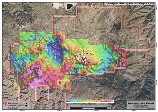
Drone Magnetic Survey (2026)
To view an enhanced version of this graphic, please visit:
https://images.newsfilecorp.com/files/8516/296914_e1e4f1acc48e7bf5_007full.jpg
The large blue area in the centre is a magnetic low. Total Magnetic Intensity Map with claim outline, roads, and drill pads indicated.
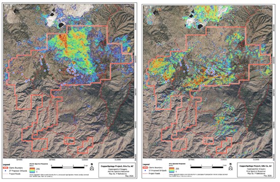
HyperSpectral - Satellite Survey
To view an enhanced version of this graphic, please visit:
https://images.newsfilecorp.com/files/8516/296914_30a3a973a46a6b71_001full.jpg
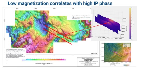
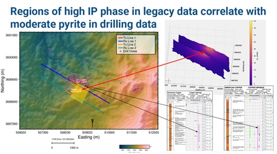
Re-Interpretation of Historical 2D IP (2007)
To view an enhanced version of this graphic, please visit:
https://images.newsfilecorp.com/files/8516/296914_30a3a973a46a6b71_002full.jpg
To view an enhanced version of this graphic, please visit:
https://images.newsfilecorp.com/files/8516/296914_30a3a973a46a6b71_003full.jpg
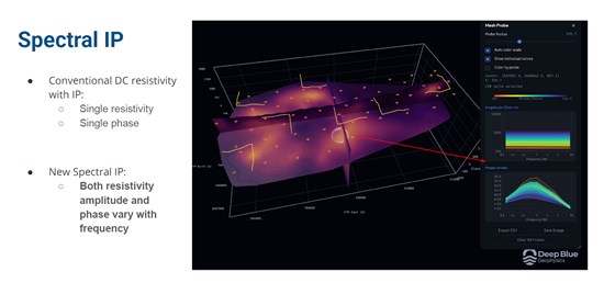
Deep Blue Geophysics Re-Interpretation
- Deep Blue employed its proprietary DeepBlueEM2D code to conduct 2D Spectral IP inversions of two legacy SIP profiles collected by Zonge in 2007. This provided a 2D model of resistivity and chargeability beneath each profile.
QUALIFIED PERSON
Michael N. Feinstein, PhD, CPG, is the "Qualified Person" under National Instrument 43-101-Standards of Disclosure for Mineral Projects, and he has reviewed and approved the scientific and technical disclosure contained in this press release. Michael is independent of the Issuer.
Zonge International completed the field work for the CSEM/SIP
- Zonge International Acquired CSEM/SIP and broadband MT data on the Copper Springs Project on a 3D grid. Vector stations of Ex, Ey were planned and setup at 59 stations. Roughly half of the stations measured Hx, Hy magnetic fields. 14 transmitter dipoles are planned to be read from 7 transmitter locations.
- The transmitted signal was a 100-percent duty-cycle square wave. Initial base frequencies were 0.125, 1, 8, and 64 Hz. Total read time was approximately 2 hours per transmitter dipole.
- All MT data was acquired from 0.01-1,024Hz, the data was collected before and after the CSEM/SIP reads. All data was acquired at 4096 samples per second.
- A distant remote reference site was deployed. The remote site was deployed away from powerlines, pipelines, and other cultural electromagnetic sources to the extent possible. A location to the SE of the grid was chosen.
- ZONGE surveyed the station locations and wire path using Garmin 64s Handheld GPS.
- All acquired field data was checked through a QA/QC review and processed daily using the Zonge CSEM and MT Processing workflow. The data was processed in two large batches. One about halfway through the project and once at the end.
- Instrumentation consisted of ZONGE broadband ZEN receivers. Magnetic field data was acquired with ZONGE ANT-4 low frequency broadband induction feedback coils. There will be spare receivers on site if possible. The receiver electrodes will consist of rusted steel plates.
- The source for the CSEM/SIP data was a Zonge GGT-10, 10 KVA transmitter system. Multiple systems were utilized to minimize delays between transmitter reads If 90% of the source-receiver combinations and 90% of the MT soundings were successfully acquired without equipment failure or operator error.
Zonge Engineering - Drone Magnetic Survey
- Zonge covered an area of 33 km2, with lines-oriented east-west at 50-meter line spacing. The approximate total coverage is 650 line-km.
- Magnetic data was acquired using a Drone-based magnetometer system. The magnetic system comprises a Geometrics MagArrow cesium vapor total-field scalar magnetometer. The platform is a battery-operated DJI Matrice 300 RTK quad-copter. The magnetometer will be attached to the drone using 3-meter suspension cables. GPS positions and total field intensity data are recorded continuously at a sample rate of 1000 Hz and reduced to 10 Hz during post-processing. Drone speed will be set between 8 and 9 m/s, depending on the terrain. The 10 Hz data sampling interval, acquired at a speed of 9 m/s, yields approximately 1 m data points along flight lines. Flight altitude will be 50m AGL. The line locations are subject to change based on flight logistics, terrain, ground access, and the UAV's line of visual sight.
- Flight paths were planned using Universal Ground Control Station terrain following software and uploaded to the UAV prior to each flight. Elevation data for flight altitude control will be sampled from USGS LiDAR terrain data.
- High winds or sudden gusts of wind can cause a pendulum motion in the tow cable, which could set the sensor out of proper orientation. The Geometrics MagArrow has two Micro-Fabricated Atomic Magnetometer (MFAM) sensors ensuring that when one sensor is in its dead zone the other is at its optimum orientation. This avoids reading dropouts during the survey. The MagArrow has a 5nT heading error, which will be compensated for by flying a calibration flight. Data was compensated using software developed by Geometrics.
- A base magnetometer recorded continuously at a fixed ground location to allow for diurnal corrections.
Copper Springs Project May 2007 Zonge Engineering 2D IP
- 250-meter dipoles were used to collect dipole-dipole frequency domain CRIP data on the two CRIP lines completed at Copper Springs. CRIP data collected in a series of receiver transmitter dipole combinations create a pseudo-depth plot referred to as a "pseudosection" (n = 1 is a shallow reading; n = 6 is the deepest). The rule is: The greater the "n" space number, the greater the depth of investigation. Resistivities are calculated from voltage measurements and the array geometry. With this dipole-dipole array it ispossible to electrically image features to depths of 750 meters with the TS2DIP inversion software developed by Zonge. Basic complex resistivity data (CRIP) were collected at 0.125 Hz. The current-controlled waveform produced by the GGT series transmitter at 0.125 Hz approximates an idealizedsquare wave. Deconvolution of the Fourier transform of digitized time-series voltage with an idealized current produces complex resistivity data. This allows four harmonic components to be calculated at the fundamental frequency of 0.125 Hz (0.375, 0.625, 0.875 and 1.125 Hz), providing a total of five measured frequencies per stack. Multiple stacks were collected at each setup.
- Dipole-dipole voltage and phase data are displayed as "Apparent Resistivity", "Raw Phase at 0.125 Hz" and "Three-frequency DC corrected Phase" (3-Pt DC Phase). Multifrequency resistivity and phase data obtained from this single frequency transmitted square wave signal provide sufficient bandwidth to correct "Raw Phase" data for array-based electromagnetic coupling. Induced polarization (IP) is determined from these corrected phase values. Other than differences due to electromagnetic (EM) coupling, phase isdirectly related to "induced polarization IP". The "Three-frequency DC" (direct current) phase correction is based on a quadratic equation defined by three frequencies: the phase at 0.125 Hz (fundamental frequency)along with the third and fifth harmonic phase data. The "zero" frequency intercept defines a phase value that approximates the IP response. Since the contribution of electromagnetic coupling is theoretically "zero" at "zero" frequency, this results in a reasonably accurate measure of induced polarization IP.
- Electromagnetic (EM) coupling levels encountered at Copper Springs were not unusual. EM coupling is proportional to frequency: CRIP data were collected at 0.125 Hz. EM coupling is proportional to the square of the dipole length: while the 250 meter dipole lengths used at Copper Springs will produce electromagnetic coupling, resistivities are reasonably high. EM coupling is inversely proportional to the survey resistivities: the moderately high resistivities encountered at Copper Springs produce minimal EM coupling. A comparison between "Raw Phase at 0.125 Hz" and "Three-frequency DC corrected Phase" (3-Pt DC Phase) pseudosections indicates the degree of the EM coupling present.
Deep Blue Geophysics - Interpretation of Zonge's Data
- Deep Blue Geophysics LLC (Deep Blue) completed specialized Data Quality Assurance/Quality Control (QAQC) and advanced 3D inversion services, for CCMM. This project focused on the integration of broadband Controlled-Source Electromagnetic (CSEM) and Magnetotelluric (MT) data collected by Zonge at the Copper Springs site.
- Deep Blue performed a rigorous audit of all Zonge deliverables to ensure the highest data integrity before modeling. This included:
- CSEM Analysis: Inspection of response data for each transmitter-receiver pair to ensure signal quality.
- MT Analysis: Systematic review of MT response data for each receiver station to identify and mitigate environmental noise or artifacts.
- Joint 3D Spectral IP Inversion Deep Blue employed proprietary DeepBlueEM3D platform to conduct a sophisticated 3D Spectral IP inversion, providing a 3D model of resistivity and chargeability. This workflow integrates the CSEM and MT data to provide a unified subsurface model.
- Integrated Dataset: Zonge CSEM and MT data was collected at approximately 59 receiver stations using 7 transmitter dipoles
- Modeling Parameters: Inversions utilized a frequency range of 0.125 Hz to 1000 Hz to resolve spectral IP (resistivity amplitude and phase).
- Staged Modeling Workflow: 1. Stand-alone 3D inversion of MT data. 2. Stand-alone 3D inversion of CSEM data. 3. Joint 3D inversion of the combined MT-CSEM dataset.
- Objective: Interpretation & Drill Targeting Following the inversion process, Deep Blue collaborated with Coyote Copper Mines to interpret the 3D volumes. This phase ensures that geophysical anomalies are cross-referenced with geological context to provide prioritized recommendations for future drill-hole locations.
HyperSpectral - Satellite Survey by Earth Daily (EDA)
EDA's Base Earth Composites (BEC) are unique multispectral datasets that have been specifically engineered to provide the best quality and data coverage over any AOI across the globe.
ASTER data, considered the workhorse of remote sensing (RS) mineral exploration, is used as the base of our Fused BEC data, contributing 6 bands of SWIR data (30 m) to the composite. This is combined with 9 bands from the Sentinel-2 multispectral (MS) dataset to provide better coverage (more bands) and higher resolution (10/20 resolution predominately) over the VNIR.
EDA's FUSED BEC's are particularly valued for greenfields exploration, as they provide early indications of mineral alteration (mapping mineral groups as indices, band ratios and (R,G,B) images at a regional scale). This results in the generation of RS maps that may target alteration.
Airborne hyperspectral data (i.e. from USGS or other suppliers), such as AVIRIS Classic is a great source of mineral mapping data, with 224 bands of continuous data with a good medium spatial resolution of 15 m.
New spaceborne hyperspectral data (i.e. PRISMA or EnMap sensors), with hundreds of bands over the VNIR-SWIR provide the capability of mineral species mapping, despite their 30 m spatial resolution. This can be a huge advantage as you have much more confidence that targeted alteration is the 'right' composition for the deposit type you are targeting.
- Data from the Bare Earth Composite (BEC) multispectral data products will provide insights on compositional variability across the Copper Springs project area. All data will be masked for water, vegetation, snow, cloud, cloud-shadow and topographic shadow (if needed), to eliminate the potential for false-positives. A suite of compositional mapping products from the BEC data will be generated for Fe-oxides, hydrothermal minerals, clays, micas, phyllosilicates and carbonates over the project AOI, and will be used to provide generalized guidance on alteration and lithology compositional characteristics across the AOI (Table 1). Additional processing will be undertaken using transforms like PCA and MNF to map any lithology or significant compositional differences across the study area.
- ASTER Emissivity data is also available and will be checked in case it is helpful for highlighting the presence of silicates (i.e. quartz), but it does have limitations at a spatial resolution of 90 m, and there may be gaps in coverage in the north. Lastly, available DEM datasets (including those from AG) will be used to provide elevation and hillshade products to combine with selected BEC products as is found to be useful for visualization.
- Fused (Bare Earth Composite) Data (all co-reg) Sentinel-2 VNIR data (10 bands) 4 bands - 10 m resolution
- 4 bands - 20 m resolution
- 1 band (coastal) - 60 m resolution
- ASTER SWIR data 6 bands - 30 m resolution
- ASTER Emissivity (TIR) 5 bands - 90 m resolution
- AVIRIS-Classic Airborne Hyperspectral (USGS 224 bands, 15 m spatial resolution
- EnMap - Spaceborne Hyperspectral (DLR) 246 bands, 30 m spatial resolution
- USGS 3Dep DEM (10 m) (for hillshade)
Neither the Exchange nor its Regulation Services Provider (as that term is defined in the policies of the Exchange) accepts responsibility for the adequacy or accuracy of this release.
This news release does not constitute an offer to sell or a solicitation of an offer to buy any of the securities in the United States. The securities have not been and will not be registered under the United States Securities Act of 1933, as amended (the "U.S. Securities Act") or any state securities laws and may not be offered or sold within the United States or to U.S. persons unless registered under the U.S. Securities Act and applicable state securities laws or an exemption from such registration is available.
Cautionary Statement Regarding Forward Looking Information
This news release contains statements which constitute "forward-looking information" within the meaning of applicable securities laws, including statements regarding the plans, intentions, beliefs and current expectations of the Corporation.
Often, but not always, forward-looking information can be identified by the use of words such as "plans", "expects", "is expected", "budget", "scheduled", "estimates", "forecasts", "intends", "anticipates", or "believes" or variations (including negative variations) of such words and phrases, or statements formed in the future tense or indicating that certain actions, events or results "may", "could", "would", "might" or "will" (or other variations of the forgoing) be taken, occur, be achieved, or come to pass. Forward-looking information includes information regarding the commencement of trading of the Resulting Issuer Shares, the business plans and expectations of the Corporation and expectations for other economic, business, and/or competitive factors. Forward-looking information is based on currently available competitive, financial and economic data and operating plans, strategies or beliefs as of the date of this news release, but involve known and unknown risks, uncertainties, assumptions and other factors that may cause the actual results, performance or achievements of the Corporation to be materially different from any future results, performance or achievements expressed or implied by the forward-looking information. Such factors may be based on information currently available to the Corporation including information obtained from third-party industry analysts and other third-party sources, and are based on management's current expectations or beliefs. Any and all forward-looking information contained in this news release is expressly qualified by this cautionary statement.
Investors are cautioned that forward-looking information is not based on historical facts but instead reflect management's expectations, estimates or projections concerning future results or events based on the opinions, assumptions and estimates of management considered reasonable at the date the statements are made. Forward-looking information reflects management's current beliefs and is based on information currently available to them and on assumptions they believe to be not unreasonable in light of all of the circumstances. In some instances, material factors or assumptions are discussed in this news release in connection with statements containing forward-looking information. Such material factors and assumptions include, but are not limited to receipt of final listing approval from the Exchange, together with the factors referenced in this news release and Filing Statement, including, but not limited to, those set forth in the Filing Statement under the caption "Risk Factors". Although the Corporation has attempted to identify important factors that could cause actual actions, events or results to differ materially from those described in forward-looking information, there may be other factors that cause actions, events or results to differ from those anticipated, estimated or intended. Forward-looking information contained herein is made as of the date of this news release and, other than as required by law, the Corporation disclaims any obligation to update any forward-looking information, whether as a result of new information, future events or results or otherwise. There can be no assurance that forward-looking information will prove to be accurate, as actual results and future events could differ materially from those anticipated in such statements. Accordingly, readers should not place undue reliance on forward-looking information.
Should one or more of these risks or uncertainties materialize, or should assumptions underlying the forward-looking information prove incorrect, actual results may vary materially from those described herein as intended, planned, anticipated, believed, estimated or expected. Although the Corporation has attempted to identify important risks, uncertainties and factors which could cause actual results to differ materially, there may be others that cause results not to be as anticipated, estimated or intended. The Corporation does not intend, and does not assume any obligation, to update this forward-looking information except as otherwise required by applicable law.

To view the source version of this press release, please visit https://www.newsfilecorp.com/release/296914

© 2026 Canjex Publishing Ltd. All rights reserved.